
Minster 400 Ton Hevistamper Straight Side Mechanical Press
ConditionUsed
1 available

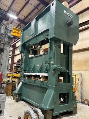
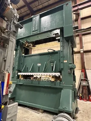
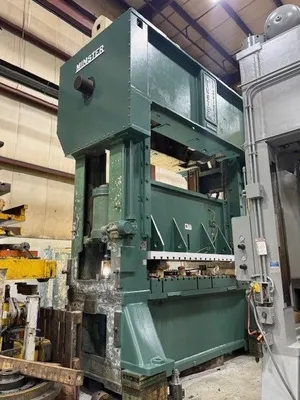
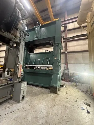
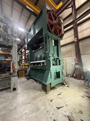


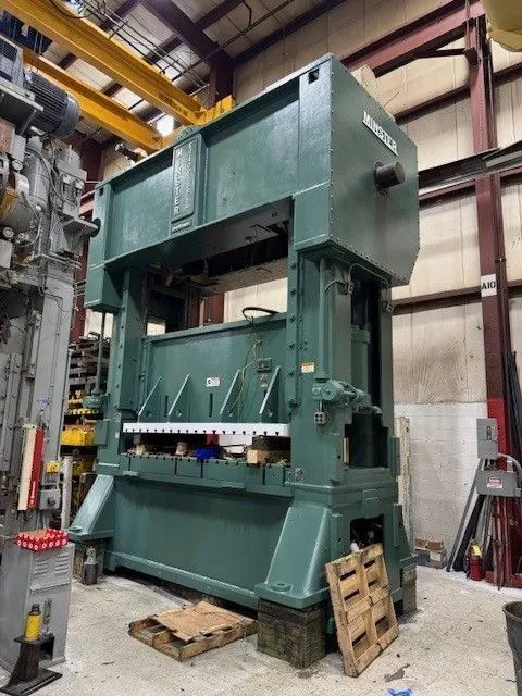
Minster 400 Ton Hevistamper Straight Side Mechanical Press, Complete Mechanical Recondition with New Toledo Press Control Package 108" x 54" Bed area, 14" Stroke, 31" Shut height over bolster plate, and 20-40 SPM.
I. Receive and offload crown, driveshaft, bull gear, pinions, and clutch/brake assembly.
II. Disassembly, clean and inspection of all components.
A. Crown Assembly
1. Disassemble and remove bull gear, turn crown over and remove main caps/crank shaft from crown.
2. Inspected crown interior for cracks. Using die penetrant Superb found no evidence of any damage/cracks.
3. Set up crown onto boring mill and checked all machined surfaces to verify crankshaft bores are parallel and square to mounting surface of driveshaft and columns.
4. Inspection found no indications of twisting. Mains were within .003 parallelism to bottom of crown mounting surfaces.
B. Bull Gears
1. Inspected both bull gears with die penetrant to find any signs of cracks.
2. Measured bore diameter to verify size and fit with crankshaft.
C. Crankshaft
1. Superb, inspected crankshaft for cracks by heat checking and applying die penetrant.
2. Measured all diameter for dimensional integrity/fit with bushings.
D. Connections
1. Inspected connections for any signs of cracks.
2. Measured upper and lower connection bores for wear and dimensional integrity/fit.
3. Superb to assemble adjustment screws onto connections to obtain/lift clearance in wrist pin/bushing in lower seats.
E. Clutch/Brake
1. Disassembled, cleaned, and inspected all components for wear and dimensional integrity.
2. Superb had to verify and account for all components due to some disassembly that had been completed prior to Superb receiving part.
F. Driveshaft/Pinions/Hardening Bone Gear
1. Clean all components prior to inspection.
2. Measured all diameters on driveshaft to verify within tolerance and fit with pinions, bearings, and herring bone gear.
3. Measure all bores in gears to verify fit and dimensional integrity.
4. Superb laid out all loose parts that came in crates to try and verify all accounted for.
Note: There may be a spacer or other details that may have to be made at time of reassembly.
III. Inspection Findings/Repairs/Reassembly
A. Crankshaft/Bull Gears
1. Right side bull gear mounting surface on crankshaft was found to be worn. Need to put crankshaft in sub arc and weld the bull gear mounting diameter.
2. R.H bull gear inner diameter is worn, need to bore for minimum cleanup.
3. Machine welded diameter on crankshaft to fit new gear I.D.
4. Cut keyway in bull gear deeper to correct depth to compensate for larger bore.
5. Polish all diameters on crankshaft to remove light scoring.
6. Furnish material, make and fit new bull gear key.
7. Upon inspection we found (8) hairline cracks in valleys between gear teeth, grind out cracks and weld.
8. Handwork and clean up weld repairs of gear teeth and paint prime.
9. L.H bull gear locking device is worn and threaded holes are damaged. Replace locking device.
B. Clutch/Brake
1. During inspection, the clutch/brake assembly was found to be missing studs and springs. Replace all with new.
2. Clutch and brake linings are worn. Reline clutch plate and replace brake lining segments.
3. Replace worn packings.
4. Assemble clutch/brake with new parts.
5. Pressure test clutch/brake, check travel, and adjust as needed.
6. Replace worn bearings in clutch housing with new.
7. Check bearing end play, weld/machine bearing spacer as needed to achieve correct end play.
C. Driveshaft
1. (1) Bushing diameter on driveshaft was previously repaired by spray/welding, the spray weld is cracking and coming off. Set up driveshaft in lathe and machine off spray/weld.
2. Set up driveshaft in sub arc to weld previously spray welded surface and weld damaged threads on left end of driveshaft. Polish all other surfaces.
3. Remove damaged driveshaft bushings from pillow block blocks.
4. Furnish material and machine new driveshaft bushings.
5. Install and fasten new bushings into pillow blocks.
6. Furnish material and make new clutch hub key.
7. Furnish material and make new pinion gear keys.
8. Install clutch/brake assembly onto driveshaft.
9. Install pinion gears, new keys, new retaining nuts and lock rings on driveshaft.
D. Flywheel Shaft
1. Set up shaft in lathe and polish.
2. Make and fit new keys for the flywheel, counterweight, and drive gear.
3. Install new bearings on flywheel shaft.
4. Install flywheel, counterweight and drive gear on flywheel shaft.
5. Set up both pillow block caps on mill and skim cut, then install caps on pillow blocks and set back up on mill and bore for minimum cleanup due to bores being worn out of round with excessive clearance. Make shim set or under pillow blocks to compensate for change in bore location after machining.
E. Flywheel Brake
1. Reline brake pad.
2. Replace packing.
3. Replace broken return spring and stud.
4. Assemble complete and pressure test.
F. Connections
1. Clean and handwork upper connection bushings.
2. Clean lube holes.
3. Clean and handwork lower connection bushings.
IV. Crown Reassembly
A. Clean and hand work main bushings.
B. Install crankshaft into crown and spot fit to ensure proper filament.
C. Install main caps and torque to spec.
D. Install connections on crankshaft.
E. Roll crown upright.
F. Install both bull gears on crankshaft.
G. Install driveshaft on crown and check for proper gear mesh and backlash to bull gears. Shim driveshaft pillow blocks as required to achieve proper mesh and backlash.
H. Install flywheel shaft assembly on crown, check drive to driven gear mesh and backlash. Shim pillow blocks as needed to achieve proper gear mesh and backlash.
I. Prep for transport.
J. Complete Update of Lubrication and Air System, includes all new filters and regulators for the air system. New Lube Pump and Motor for the lubrication system. Replace specific lube lines, external, that show any sign of requiring replacement. Check all lube blocks and make sure that they are clean and properly circulating the lube throughout the press. Any questions blocks will be replaced with new.
K. Includes a brand new Toledo Integrated Systems Press controller with Die Protection (8 input), Programmable Outputs (8 Outputs), Tonnage Monitor, in a floor standing console.
Model Number: E2-400-108-54
Serial Number: E2-400-16968
Bed Area: 108” x 54”
Slide Area: 108” x 54”
Stroke: 14”
Strokes per Minute: 20-40
Shut Height: 40” over bed
Shut Height: 31” over bolster plate
Bolster Plate: 9” thick t-slotted plate
Slide Adjustment: 10”
Windows: 38” wide approx..
Footprint Dimensions: 152” LR x 90” FB
Overall Height: 20’6” floor to top of motor
Floor Standing
Note: All crown and connection arm assembly, Clutch/Brake and Flywheel Assembly were completely rebuilt by Superb Machine Repair.
Air Clutch and Brake Assembly
Model#: 132-GC
Air Counterbalances
Hydraulic Tie Rod Nuts
Recirculating Lube System
T-Slotted Ram and Bolster
Dual Ross Valve
8 Point Gibbing
Floor Standing
Motors and Controls
New Toledo Integrated Systems Press Controller
8 Input Die Protection
Tonnage Monitor
8 Programmable Outputs
Floor Standing Console Mounted
AC Variable Speed Drive and Motor
We use cookies to improve your experience. Privacy Policy.